Bulkhead Connector Bypass Step by Step

Moderator: Moderators

Post Reply
User avatar
Steve
Posts: 7307
Joined: Wed Feb 01, 12 7:19 pm
Location: Scotland

Bulkhead Connector Bypass Step by Step

Post by Steve »

Finally got the bypass done on my car but had to do a lot of digging to work out the details of exactly what wiring to use etc so thought it might be a good idea to post exactly what I used (it works thankfully). Obviously it would be great if some info could be added to this as I have been learning as I go along so some bits might not be exactly as others have done it....here goes;

Firstly, and thanks to Daves repeated posting of the MAD conversion thread, I based the bypass on the info contained in it....here it is again

http://www.madelectrical.com/electrical ... uges.shtml

The basic concept of this conversion is detailed in the above link so I wont go into that...its a good, easy read to be honest..

1. Prep....I stripped all the tape off the section of wiring loom I was working on between the starter relay and the bulkhead connector just so I knew for sure I was cutting the correct cables etc, end to end. I also decided to run the new cables through an existing bulkhead grommet rather than through drilled holes in the bulkhead connector. I did this so that I can still take the connector apart without having the solid cable running through it. I also disconnected the battery and removed it from the car

2. I ran a length of 65-0.30 (65 strand 0.30 =metric gauge) http://www.ebay.co.uk/itm/DURITE-AUTOMO ... 43a9faabc1 from the back of the alternator stud, around the bulkhead loom and to the starter relay positive post (the large top one with large nut on it). I put the correct size terminal on the alternator end and just prior to the relay, I fitted a Ford Alternator Fuseable Link http://www.ebay.co.uk/itm/Genuine-Ford- ... 483e609455 with the correct size connector on it. This now means the power from the alternator is going directly to the battery, via the starter relay, instead of from the alternator, through the bulkhead connector to the ammeter, back out the bulkhead connector and into the relay. The old black wire from the alternator is now no longer in use within the engine bay.

3. Next, snip the red wire at terminal 'J' on the bulkhead connector. Disconnect the other end of this wire from the starter relay and bin it. Then push a length of red 65-0.30 wire through the bulkhead grommet, into the drivers footwell and pull about 12" through to work with. Run this wire along the wiring loom to a position near to the starter relay.

4. Find a spot near to the starter relay and screw a fuse holder with a 40 amp flat fuse in it to the fender wall or similar http://www.ebay.co.uk/itm/1-x-MIDI-TYPE ... 4abe0ddc46. Take the end of the 65-0.30 wire you have just fitted and fit a ring connector of the correct size to it and bolt it onto one side of the fuse holder. Make a small lead using the same wire, with another ring connector on it for the other side of the fuse holder and a larger ring connector to fit the positive stud on the starter relay. Then go to the back of the bulkhead connector, cut the other side of the red wire at pin 'P' and solder and heat shrink the new red wire onto the old wire within the dash loom.

5. Now splice a length of black 44-0.30 http://www.ebay.co.uk/itm/5m-LENGTH-BLA ... 2c61be4d7e wire into the new red wire somewhere between the bulkhead grommet and the new fuse holder you have installed. Push this wire through the bulkhead grommet alongside the previously installed red wire. Snip the black wire from both sides of terminal 'P' and join the new black wire into the old black wire in the dash loom. Take the old black wire off the starter relay and bin it. I had to remove the small purple wire from the same connector that the black wire used at the relay and fit a new ring connector to it and refit it to the starter relay positive stud. I think this runs to the horn relay???

6. Finally, remove the wires from the back of the ammeter (Red and Black) and join them together. Bin the old wire that ran from the alternator to terminal 'P' in the bulkhead connector and once tested, tape loom up etc, start car, test alternator output....job done!

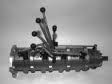
I've stuck some pics on and the titles are self explanatory I hope. Would appreciate someone (the more the merrier) just going through this with a fine tooth comb and making sure I haven't missed anything please. Works in my car but want to be sure its correct for everyone.

Thanks for all the help Ive had doing this gents and good luck....if I can do it anyone can!!

Cheers Steve :thumbright:
Attachments
fuse holder.jpg
fuse holder.jpg (110.67 KiB) Viewed 2630 times
Ford alternator fused link.jpg
Ford alternator fused link.jpg (95.58 KiB) Viewed 2630 times
alternator cable (new).jpg
alternator cable (new).jpg (102.79 KiB) Viewed 2630 times
alternator bolt (old).jpg
alternator bolt (old).jpg (123.71 KiB) Viewed 2630 times
Last edited by Steve on Sun Nov 04, 12 12:03 pm, edited 7 times in total.
Bat Girl Stalker Living Petes Dream
User avatar
Steve
Posts: 7307
Joined: Wed Feb 01, 12 7:19 pm
Location: Scotland

Post by Steve »

Some more pics....
Attachments
starter solenoid prior to conversion.jpg
starter solenoid prior to conversion.jpg (105.97 KiB) Viewed 2628 times
fuse to starter relay cable.jpg
fuse to starter relay cable.jpg (38.52 KiB) Viewed 2628 times
fuse holder finished.jpg
fuse holder finished.jpg (85.4 KiB) Viewed 2628 times
fuse holder wired in.jpg
fuse holder wired in.jpg (109.69 KiB) Viewed 2628 times
Bat Girl Stalker Living Petes Dream
User avatar
Steve
Posts: 7307
Joined: Wed Feb 01, 12 7:19 pm
Location: Scotland

Post by Steve »

and finally.....
Attachments
wiring loom splice.jpg
wiring loom splice.jpg (103.53 KiB) Viewed 2625 times
starter relay finished.jpg
starter relay finished.jpg (87.63 KiB) Viewed 2625 times
bulkhead grommet.jpg
bulkhead grommet.jpg (90.62 KiB) Viewed 2624 times
Bat Girl Stalker Living Petes Dream
User avatar
Steve
Posts: 7307
Joined: Wed Feb 01, 12 7:19 pm
Location: Scotland

Post by Steve »

Just to clarify a couple of the pics....the fuseable link in the relevant pic is the thin black wire with white writing on it (sorry not too clear) and in the spliced wire pic, you can see where its joined where the black tape is and the black wire is just showing under it heading towards the bulkhead. I had this joined in at the auto electricians shop I use as its an important splice and my soldering skills aren't great.... :oops:

Cheers Steve :thumbright:
Bat Girl Stalker Living Petes Dream
User avatar
AllKiller
Posts: 15191
Joined: Fri Jun 04, 04 9:33 pm
Location: Hampshire

Post by AllKiller »

Nice Job, good detailed explanation :thumbright:
ALL KILLER NO FILLER
Nostalgia, its not what it used to be.

Carbon footprint of a Saturn V
Image
User avatar
Steve
Posts: 7307
Joined: Wed Feb 01, 12 7:19 pm
Location: Scotland

Post by Steve »

Here are a few pics of the cable routing before taping it up....want to rewire the starter leads this week and install the mini starter when it arrives and make sure it all works before I tidy everything up and Bananarama! off. and Im going to paint the yellow connectors black cos they are horrible!!!

Cheers Steve :thumbright:
Attachments
wiring loom at starter relay.jpg
wiring loom at starter relay.jpg (105.58 KiB) Viewed 2587 times
wiring loom on fender 1.jpg
wiring loom on fender 1.jpg (93.66 KiB) Viewed 2587 times
wiring loom at bulkhead connector.jpg
wiring loom at bulkhead connector.jpg (100.39 KiB) Viewed 2587 times
Bat Girl Stalker Living Petes Dream
User avatar
Dave81
Posts: 7103
Joined: Fri Jul 23, 10 4:01 pm
Location: Worcestershire

Post by Dave81 »

Good write up Steve.

Another project on the list of things to do on mine! :thumbright:
Dave Tildesley.....MMA-081
72 Dodge Dart
73 Plymouth Duster - SOLD

I wanna go so FAST i think i'm going to DIE!..........Then i'll shift into second!

"My Car is a work in progress, Probably never gonna get finished, never gonna have the money to Bananarama!!"
User avatar
Steve
Posts: 7307
Joined: Wed Feb 01, 12 7:19 pm
Location: Scotland

Post by Steve »

Cheers Gents.... Found the research on this quite frustrating.... Think we all know it needs to be done but the actual mechanics of what to use and exactly what to do in plain language, is open to interpretation. Felt pointless doing it then not sharing it all, even if its just the basic conversion, open to a bit of improvement as we go along and other suggestions on materials etc,

Cheers Steve :thumbright:
Bat Girl Stalker Living Petes Dream
User avatar
Charger
Posts: 5137
Joined: Mon Dec 12, 05 11:40 am
Location: Manchester, UK MMA/921

Post by Charger »

nice one Steve :thumbright:
Si
1970 Charger 500
383 | 4bbl | 727 column | PAS | PAB | buckets/buddy - check out my photos HERE

If you don't want another same old brand-new car ... you could be DODGE MATERIAL

1970 Dodge Charger Registry - https://www.1970chargerregistry.com/
User avatar
autofetish
Posts: 5599
Joined: Sat May 21, 11 6:43 am

Post by autofetish »

Great stuff :thumbright: :thumbright:
User avatar
MattH
Posts: 5796
Joined: Sun Apr 18, 04 10:56 pm
Location: Bedfordshire

Post by MattH »

I'm going to do this whilst i'm under the bonnet, as my lights are S**T and driving in the dark last week flattened the battery, so i suspcet the alternator circuit is rather crusty.

Just wondered if bypassing the ammeter, there is a way of making it a voltmeter, or is it best just to not have anything, i.e no charging indicator.

I read the MAD post and it seems most just bypass the ammeter and don't have it working, just carry jump leads in the boot!
Matt Hollingsworth - Vehicle Registrar
Panther Pink 73 Aussie Charger 265 Hemi 4 spd
Challenger Sam Posey Tribute car
User avatar
Pete
Posts: 21949
Joined: Sun Apr 18, 04 10:49 pm
Location: MMA Chairman

Post by Pete »

You can wire a voltmeter to any point where there is a switched 12V supply and ground.

The tiny digital ones are quite cool and only around £3.50 off eBay............
Pete Wiseman; Cambridge.

Mopar by the grace of God
User avatar
Dave999
Posts: 9432
Joined: Thu Feb 24, 05 10:31 am
Location: Twickenham,London, England

Post by Dave999 »

MattH wrote:I'm going to do this whilst i'm under the bonnet, as my lights are S**T and driving in the dark last week flattened the battery, so i suspcet the alternator circuit is rather crusty.

Just wondered if bypassing the ammeter, there is a way of making it a voltmeter, or is it best just to not have anything, i.e no charging indicator.

I read the MAD post and it seems most just bypass the ammeter and don't have it working, just carry jump leads in the boot!

only need to bypass it if you swap to a bigger AMP hour battery and an alternator that puts out more than 36 Amps

if the insulation is good and the connections are tight at the ammeter and bulkhead it should be fine. araldite the connectors on the back and they wont come undone

its the wrong rating of ammeter for conversion to a volt meter, for the needle to move the meter (well parts of it) would still need to pass 0-30 amps thus defeating the object of the exercise.

lights can be addressed by using the 12 volt feeds from the switch to power to 2 relays. feed lamps from battery via new fuse box with relay contacts as their switch. and use halogen bulbs


Dave
The Greater Knapweed near the Mugwort by the Buckthorn tree is dying
User avatar
MattH
Posts: 5796
Joined: Sun Apr 18, 04 10:56 pm
Location: Bedfordshire

Post by MattH »

I was considering relays for the lights as well, but thought the fact that everything feeds through the ammeter would cause extra problems elsewhere.

I think I will do both jobs, to fireproof the car, improve the charging and improve the lights.

It does have a slightly bigger AH battery but stock alternator.
Matt Hollingsworth - Vehicle Registrar
Panther Pink 73 Aussie Charger 265 Hemi 4 spd
Challenger Sam Posey Tribute car
User avatar
Dave81
Posts: 7103
Joined: Fri Jul 23, 10 4:01 pm
Location: Worcestershire

Post by Dave81 »

I put a Sunpro triple gauge setup on mine Matt. Has Voltmeter and added bonus of a Mech temp gauge via capillary.

I had charging issues and temp issues (all sorted now), but its nice to know exactly what is going on for power and temp.

Got it off of Amazon........only cost me circa £30 from memory.

Have pressure gauge for oil, but its not hooked up........

Here you go........Not exactly expensive:


Installed on mine:
Image
Dave Tildesley.....MMA-081
72 Dodge Dart
73 Plymouth Duster - SOLD

I wanna go so FAST i think i'm going to DIE!..........Then i'll shift into second!

"My Car is a work in progress, Probably never gonna get finished, never gonna have the money to Bananarama!!"
Post Reply